Figure 1. Wiring a Commodore tape interface to the Oric-1. From left to right: READ (red), VCC, GND, WRITE (white). The ICs on top are memory, and the IC on the right is the sound chip.
The Commodore 8-bit line of microcomputers and the Oric-1 have one thing in common: both are based on the 6502 architecture. Everything else is totally different, starting from the cassette drive connection (and tape format). The Oric-1 was designed to use a regular tape deck with line-level input and output, while Commodore uses a dedicated C2N datassette that uses TTL levels and is powered from the cassette connector.
Luckily, there is a spot on the Oric-1 circuit board that almost provides a Commodore-style datassette interface. Slightly to the front left from the rightmost DRAM chip, there is a via for the TTL-level cassette read line. There are vias for VCC and GND nearby, and the TTL-level cassette write line is at the right leg of a resistor. See Figure 1.

Figure 1. Wiring a Commodore tape interface to the
Oric-1. From left to right: READ (red), VCC, GND, WRITE (white). The
ICs on top are memory, and the IC on the right is the sound chip.
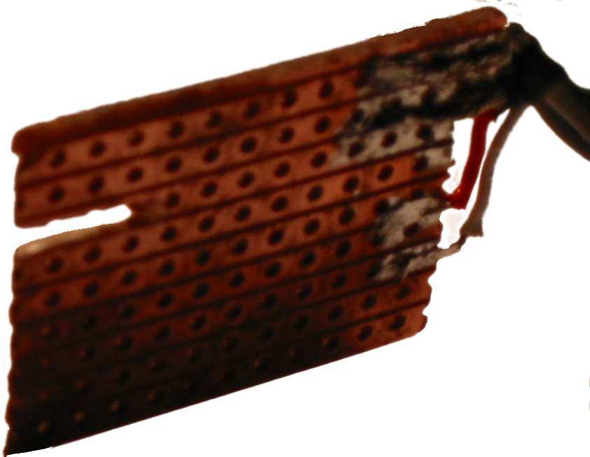
The Commodore datassette has an edge connector with 3.96mm spacing. The connector can be manufactured from a prototyping board with 2.54mm spacing, as Figure 2 illustrates.

Figure 2.
Home-made Commodore tape drive connector. From top to bottom: GND,
VCC, tape motor (unassigned), READ (red), WRITE (white), SENSE
(unassigned).
Unfortunately, the tape motor cannot be directly driven from the VCC supply of the Oric-1, because it probably causes too much disturbance to prevent the 6502 from starting properly. It would be better to use a separate power supply for the tape motor. In 8-bit Commodore computers, the voltage for the motor is 6 volts, unregulated.
The SENSE line can be ignored. The Commodore datassette connects it to ground whenever a switch (PLAY, F.FWD, REWIND) is closed.